EP0636281B1 - Vielpoliger steckereinsatz - Google Patents
Vielpoliger steckereinsatz Download PDFInfo
- Publication number
- EP0636281B1 EP0636281B1 EP94907557A EP94907557A EP0636281B1 EP 0636281 B1 EP0636281 B1 EP 0636281B1 EP 94907557 A EP94907557 A EP 94907557A EP 94907557 A EP94907557 A EP 94907557A EP 0636281 B1 EP0636281 B1 EP 0636281B1
- Authority
- EP
- European Patent Office
- Prior art keywords
- connector insert
- contact
- connector
- insert according
- contacts
- Prior art date
- Legal status (The legal status is an assumption and is not a legal conclusion. Google has not performed a legal analysis and makes no representation as to the accuracy of the status listed.)
- Expired - Lifetime
Links
Images


Classifications
-
- H—ELECTRICITY
- H01—ELECTRIC ELEMENTS
- H01R—ELECTRICALLY-CONDUCTIVE CONNECTIONS; STRUCTURAL ASSOCIATIONS OF A PLURALITY OF MUTUALLY-INSULATED ELECTRICAL CONNECTING ELEMENTS; COUPLING DEVICES; CURRENT COLLECTORS
- H01R24/00—Two-part coupling devices, or either of their cooperating parts, characterised by their overall structure
- H01R24/76—Two-part coupling devices, or either of their cooperating parts, characterised by their overall structure with sockets, clips or analogous contacts and secured to apparatus or structure, e.g. to a wall
- H01R24/78—Two-part coupling devices, or either of their cooperating parts, characterised by their overall structure with sockets, clips or analogous contacts and secured to apparatus or structure, e.g. to a wall with additional earth or shield contacts
-
- H—ELECTRICITY
- H01—ELECTRIC ELEMENTS
- H01R—ELECTRICALLY-CONDUCTIVE CONNECTIONS; STRUCTURAL ASSOCIATIONS OF A PLURALITY OF MUTUALLY-INSULATED ELECTRICAL CONNECTING ELEMENTS; COUPLING DEVICES; CURRENT COLLECTORS
- H01R2107/00—Four or more poles
-
- H—ELECTRICITY
- H01—ELECTRIC ELEMENTS
- H01R—ELECTRICALLY-CONDUCTIVE CONNECTIONS; STRUCTURAL ASSOCIATIONS OF A PLURALITY OF MUTUALLY-INSULATED ELECTRICAL CONNECTING ELEMENTS; COUPLING DEVICES; CURRENT COLLECTORS
- H01R31/00—Coupling parts supported only by co-operation with counterpart
- H01R31/02—Intermediate parts for distributing energy to two or more circuits in parallel, e.g. splitter
-
- H—ELECTRICITY
- H01—ELECTRIC ELEMENTS
- H01R—ELECTRICALLY-CONDUCTIVE CONNECTIONS; STRUCTURAL ASSOCIATIONS OF A PLURALITY OF MUTUALLY-INSULATED ELECTRICAL CONNECTING ELEMENTS; COUPLING DEVICES; CURRENT COLLECTORS
- H01R31/00—Coupling parts supported only by co-operation with counterpart
- H01R31/08—Short-circuiting members for bridging contacts in a counterpart
Definitions
- Multipole plug insert in particular for installation in a plug housing, with mounting flanges being provided on the plug insert and fastening bases on the plug housing - the plug insert comprising a first part which has a first number of contact inserts located in insertion openings, and a second part which comprises a second, compared to the first multiple number of connection contacts seated in connection openings, each contact insert in the first part being permanently conductively connected to at least two connection contacts in the second part, and in the second part in each case between two adjacent groups of at least two connection contacts, each with a contact insert in the the first part are permanently connected, an opening is provided into which a contact clip can be clamped. which establishes a conductive connection between the two adjacent groups of at least two connection contacts.
- Plug inserts of the type mentioned above are used in a variety of ways in the field of industrial control and regulation. They are often combined into several in a parallel arrangement in switch boxes.
- the respective plug insert or the respective add-on housing is inserted into the control cabinet in such a way that plug contacts - pins or sockets - point outwards for connection with a mating connector, while the desired wiring is carried out on the inside via corresponding connection contacts.
- the connection contacts can be screw contacts, flat plug contacts, crimp contacts, spring-loaded Clamp contacts, solder contacts or the form of termi-point (connection for clamping shoe) or wire-rap (connection for winding technology).
- a multi-pole plug insert of the type mentioned in which in each case one plug contact element is connected to a plurality - ie in particular four - line connection elements.
- Bridge elements can be plugged onto adjacent line connection elements in such a way that all line connection elements of two adjacent plug contact elements are connected in an electrically conductive manner and are therefore at the same potential.
- Two of the previously available - a total of eight - line connection elements of two adjacent plug contact elements are thus occupied, so that now only a reduced number - six - remains free for conductors to be connected.
- 25% of the available line connection elements are lost when a bridge circuit is made.
- Another disadvantage is that the manufacture of a bridge circuit with fully occupied Line connection elements is not possible.
- the opening is designed such that when the contact clip is clamped in, the connection contacts remain unoccupied, so that they retain a connection possibility for connecting wires when the contact clip is clamped in.
- each plug-in contact in the first part is in each case permanently conductively connected to two connection contacts in the second part. This corresponds to the need that occurs most frequently, so that in the following it will only be referred to. Deviating from this, it is also possible that each plug contact in the first part with a larger number, for. B. four connection contacts each, is permanently conductively connected in the second part if there is a corresponding need. According to the invention, the possibility is created to selectively establish conductor connections between a larger number of connection contacts with one another by means of suitable contact clips. This type of contact bracket will be discussed later.
- the first part comprises two parallel rows of plug contacts and the second part four parallel rows of connection contacts, each of the same number.
- the main focus here is on add-on housings for 6, 10, 16 or 24-pin connectors.
- the idea according to the invention can also be applied to plugs which, for example, only have a number of plug contacts in the area of the first part and have several, in particular two rows of connection contacts in the second part.
- the design of the plug insert according to the invention consists in that in the second part, an opening is provided between two groups of permanently conductively connected connection contacts, into which a contact clip can be clamped, which provides a conductive connection between the two adjacent groups of connection contacts which are always conductively connected to one another manufactures.
- inelastic contact pins can also occur, which interact with resilient contact edges of the conductors.
- the plug insert consists of at least two parts and is divided in the second part in a main division plane perpendicular to the through openings of the plug insert and has corresponding recesses into which conductor elements can be inserted, which can then be inserted can be fixed by assembling the two parts, and serve for the conductive connection of the plug contacts with the respective connection contacts.
- the two made of non-conductive material Parts of the second part of the plug insert can be secured against one another by means of clamp connections or adhesive connections.
- the plug insert is composed of a plurality of disk bodies, each of which comprises the first and second part and whose main parting planes are parallel to the through openings of the plug insert and have the corresponding recesses, between which each other Conductively connected plug contacts and connection contacts can be inserted, which are then held by the assembly of two of the disk body.
- the large number of disc bodies made of non-conductive material can be connected to one another in a simple manner by means of rivet or screw connections which are pushed through transversely to the disc planes.
- the supervisory surface of the second part protrudes perpendicular to the insertion direction over the cross section of the first part, in this case it is particularly advantageous if the first connection surface provided with insertion openings for the contact inserts on the one hand and the insertion openings for the Connections provided second pads on the other hand are parallel to each other and point in opposite directions. In a further advantageous embodiment it is provided that the second connection surfaces are coplanar.
- the insertion openings for the contact inserts provided on the one hand and the second connection surfaces provided with insertion openings for the contacts on the other hand form an angle. It is according to the installation conditions possible that the second pads are offset parallel to each other or that the second pads are roof-shaped to each other and symmetrical to the first pad.
- the first part can be inserted into the inner cross section of the through opening and the second part adjoins the first outside the through opening and via the inner cross section of the Through opening protrudes.
- Such a plug insert can be inserted into a conventional plug housing, in particular an add-on housing, so that in this respect no special adaptation of the surroundings of the plug insert is necessary.
- the first part of the plug insert can be equipped with contact pins or contact sockets in a known manner.
- the inventive design of the second part of the plug insert gives each contact pin or contact socket the possibility of multiple separate assignment with connecting wires. Due to the widened configuration of the second part of the plug insert, the corresponding connection contacts have the usual dimensions, in particular the usual distances between them, so that there is a very favorable access option.
- the first and second part of the plug insert have essentially the same length, so that the second part projects laterally in width across the attachment housing.
- the plug insert Due to the shape of the plug insert according to the invention, it must be inserted into a suitable standard mounting housing from behind. Also preferably from behind, based on the add-on housing, the plug insert is screwed relative to the same. It follows from this that the wiring is expediently connected to the separate plug insert, which is then inserted from the wiring side into the attachment housing, which may already be installed in the control cabinet.
- the cross section of the second part in the direction of its insertion openings corresponds approximately to the cross section of the first part perpendicular to its insertion openings.
- first connection surface of the first part provided with the openings for the plug contacts it is possible for the first connection surface of the first part provided with the openings for the plug contacts to form an angle with one another with respect to the second connection surfaces provided with the connection openings for the connection contacts. It is possible that the first connection surfaces on the one hand and the second connection surfaces on the other hand form an angle of 90 ° with one another, the connection surfaces being coplanar with one another or that the first connection surface on the one hand and the second connection surfaces on the other hand form an angle between 90 ° and 180 ° with one another form.
- the first part can be inserted into the inner cross section of the through opening and the second part adjoins outside the through opening with a cross section that can be passed through it.
- the aforementioned plug inserts can be inserted into an attachment housing either from the front or from the rear.
- a small tilting movement is required to guide the corresponding mounting flanges past the bases in the installation housing.
- the fastening flanges when inserted from the front, also rest on the front in the attachment housing, while when inserting from the rear, the fastening flanges rest on the base arranged in the attachment housing in the usual manner.
- the screw connection can be carried out either from the front or from the rear, depending on whether the base is provided with a through hole and the reinforced screwed-on flanges are provided with a threaded hole or vice versa.
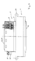
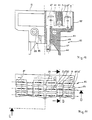
- FIGS. 1 and 4 show a cross section through a conventional add-on housing 1 and a plug insert 2 according to the invention used therein.
- the plug insert 2 has mounting flanges 26 which rest on bases 38 in the attachment housing 1 and are connected to the latter by means of screws 27 shown only by means of center lines.
- the plug insert 2 comprises a first part 4 inserted into the through opening 3 of the attachment housing 1, and a second part 5 lying outside the same and projecting beyond the open cross section of the attachment housing 1.
- the first part 4 merges in one piece into a base plate 6 of the second part 5 .
- This has a side frame part 7.
- Inserts 8 are fitted into the frame part.
- pairs of insertion openings 9 are provided, into which contact sockets 10 are inserted.
- the plug insert 2 of the form shown here has a first connection surface 13 with the insertion openings 9 for the contact inserts and two parallel connection surface parts 22, 23, which are coplanar and symmetrical to one another, with the insertion openings 19 for connection contacts, the first connection surface 13 and the second pads 22, 23 are directed opposite to each other.
- FIGS. 2 and 5 details corresponding to those in FIGS. 1 and 4 are designated with the same reference numbers.
- the reference numbers are predominantly only entered in the enlarged representation according to FIG. 5.
- the top view of the add-on housing 1 can be seen, which has at its ends flanges 25 with through holes 24 for pushing through screws for fastening the housing to a switch cabinet housing or the like.
- fastening flanges 26 are screwed onto the base 38 in the through opening 3 by means of screws 27.
- Sheet metal parts are fastened on the end face to the plug insert 2, forming tabs 28, 29, one of which is equipped with a holding plate 30 and a clamping screw 31, while in the other only a threaded hole 32 can be seen. Earthing or protective contact conductors can be connected to these tabs.
- the plug insert 2, of which the second part 5 is visible is partly shown in view, partly with the cover part 14 being broken away.
- the peripheral frame part 7 is shown without breaking out.
- the conductor rails each have laterally broken-out contact edges 33, into which contact brackets 20 can be snapped in and can be used to produce a conductive contact between two adjacent conductor rails 11 lying in parallel.
- These contact brackets 20 comprise resilient conductor legs 34 lying in parallel. Four of these contact brackets can be seen in section in the cutaway representation previously discussed.
- the openings 18, 18 'for the clamping screws and the openings 19, 19' for inserting the conductor wires can be seen in the view. Between two rows of the openings mentioned, further openings 21 are arranged, into which the aforementioned contact brackets 20 can be inserted. In the view, four of the contact brackets 20 are shown with their handle parts 35 lying on top.
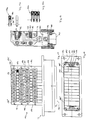
- FIGS. 3 and 6 corresponding details are given the same numbers as in the other figures. The major part of the details is only entered in the enlarged representation of FIG. 6.
- the attachment housing 1 with flanges 25 with the through holes 24 can be seen, in which the plug insert 2 is inserted as in the previously mentioned figures.
- This is inserted with its first part 4 in the through opening 3 of the attachment housing 1, and protrudes from the bottom of this.
- the upper wider second part 5 is shown in partial section.
- the through opening 3 has a central axis A.
- the holding plate 30 and the clamping screw 31 can be seen on the left.
- the second part 5 with the frame 7, in which the cover part 14 is inserted precisely recognize.
- the conductor rails 11 are inserted and held, on which the laterally broken contact edges 33 can be seen.
- the contact bracket 20 are inserted, which have a non-conductive handle part 35 and two resilient conductor legs 34, which are conductively connected to one another in a U-shape and are cast in the handle part 35.
- the free conductor legs 34 run against a wedge 37 in the base plate 6, which ensures that the legs 34 make conductive contact with the contact edges 33 of two conductor rails 11 lying parallel to one another.
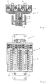
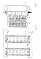
- Figures 7 and 10 and 8 and 11 are jointly described below. Individual reference numbers can only be found in one or the other of the figures described together.
- Figure 7 corresponds to a section along the section line AB from Figure 8
- Figure 10 corresponds to a section along the section line CD from Figure 11
- Figure 12 corresponds to a section along the section line AB from Figure 11.
- a plug insert 52 is shown partially (FIG. 10) or completely and inserted into a conventional add-on housing 51 (FIG. 7).
- the plug insert 52 has fastening flanges 76 which rest on bases 88 in the attachment housing 51 and are connected to the latter by means of screws 77.
- the plug insert 52 includes a in the through opening 53 of the Add-on housing 51 inserted first part 54, and a second part 55 lying outside of add-on housing 51 and projecting over its open cross-section.
- the lower section of the first part is formed by a contact insert 89, which is not shown in FIG.
- the first part 54 merges in one piece into the second part 55 in the sectional plane shown in FIG. 10.
- Openings 59 in the form of longitudinal recesses are provided in the plug insert 52, into which conductor rails 61 are inserted.
- Contact pins 60 are pushed onto these and crimped on at the bottom.
- the conductor rails 61 merge in one piece into connection contacts 67, 67 '. They also have middle contact tongues 62.
- the conductor rails 61 are punched out of sheet metal.
- the connection contacts 67, 67 ' end in open insertion openings 69, 69' for suitable flat plugs.
- the contact tongues 83 are in the region of insertion openings 71 for contact brackets which will be shown later.
- Longitudinal bores 98 are formed in the plug insert 52, through which rivets 99 can be pushed for connecting several disk-shaped parts of the plug insert.
- the plug insert 52 of the form shown here has a connection surface 63 with the openings 59 for the contact inserts and two connection surface parts 72, 73 lying parallel thereto, which are coplanar and symmetrical to one another, with the insertion openings 69 for connection contacts, the connection surfaces 63 and the connection surfaces 72, 73 lie opposite to each other.
- FIGS. 8 and 11 details corresponding to those in FIGS. 7 and 10 are designated by the same reference numbers.
- the plug insert 52 is shown in a top view, the attachment housing 51, into which the plug insert 52 is inserted, being visible in FIG.
- the attachment housing 51 shows at its ends flanges 75 with through holes 74 for inserting screws with which the attachment housing 51 on a control cabinet housing or the like can be screwed.
- fastening flanges 76 of the plug insert 52 are screwed onto the aforementioned bases 88 of the attachment housing by means of screws 77.
- FIG. 11 shows that the plug insert is made up of front-side washer bodies 56 ', 56' and further washer bodies 56 which are identical to one another.
- the designation disc body does not conflict with the fact that springs and grooves 96, 97 join into one another in the end faces.
- the insertion openings 69, 69 ' can be seen between the disk bodies, in which the connection contacts 67, 67', which are designed as tongue-shaped sheet metal parts, are free. Standard flat plugs can be attached to these.
- the insertion openings 71 into each of which the contact tongues 83 protrude at the end, lie outside the section plane shown in FIG. If a contact clip is inserted into one of these openings 71, adjacent pairs of connection contacts 67, 67 'are conductively connected to one another via the establishment of a conductive contact between the corresponding contact tongues 83, e.g. B. the designated with 1 - 1 connection contacts with the parallel contacts, to which the numbers 2 - 2 are to be assigned mutatis mutandis.
- FIG. 9 shows the plug insert 52 installed in the attachment housing 51 without any particular details, the first part 54 and the second part 55, which protrudes above, protruding from the through opening. It is indicated that the plug insert 52 as a whole is made up of washer bodies 56 of the same type with one another and two front washer bodies 56 ', 56 ", each of which is the entire height of the first and second Include parts. In contrast, the part of the plug insert for contact pins or contact sockets protruding from the through opening is in one piece. The central axis A of the through opening is particularly marked.
- FIG. 12a shows a section through the upper part of the second part 55 of a plug insert.
- the insertion openings 71 can be seen, these being located between individual disk bodies 56, which, viewed in this sectional plane as well, engage one another with mold engagement means 94, 95, without this contradicting the designation as a disk body.
- the contact tongues 83 with openings 86 each lie on the end face in the insertion openings 71.
- Parts of the contact bracket 70 shown in detail in FIG. 12b engage in the openings 86 and have a non-conductive handle part 85 and two resilient conductor legs 84 which are connected to one another in a U-shaped manner and are cast on the handle 85.
- expressions 87 of the conductor legs 84 snap into the openings 86 of the contact tongues 83. In this way, conductive contact is established between adjacent pairs of connection contacts 67, 67 '.
- FIGS. 13a and 13b are described together below.
- the reference numbers mentioned are increased by 100 compared to corresponding parts from the illustration in FIGS. 1 and 4.
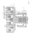
- FIGS. 13a and 13b show a cross section through a conventional add-on housing 101a between 101b and a plug insert 102 according to the invention used therein.
- the plug insert 102 has screwed-on fastening flanges 126 which rest on bases 138a and 138b in the add-on housing 101 and are connected to the latter by means of screws 127.
- the bases 138a according to FIG. 13a are located to the front on the plug side in the housing 101a; the mounting tabs 126 are for assembly and screwing the plug insert 102 on them from behind.
- the bases 138b according to FIG. 13b are set back from the plug side deeper in the housing 101b; The assembly of the plug insert 102 and its screwing can be done from the front.
- the plug insert 102 comprises a first part 104 inserted into the through opening 103 of the attachment housing 101, and a second part 105 lying outside the same and fitting into the open cross section of the attachment housing 101.
- the first part 104 merges in one piece into a base plate 106 of the second part 105 .
- This has a lateral frame part 107.
- a cover part 114 is fitted into the frame part.
- openings not shown in pairs, are provided, in which contact sockets are inserted. These are in contact with conductor rails 111, which are divided into first contact tongues 112 and second contact tongues 112 ', only half of the second part being numbered.
- the conductor rails 111 are held between the base plate 106 and the cover part 114.
- the previously mentioned parts are each provided in a symmetrical design with respect to a central plane E of the second part 105.
- the cover part 114 inserted into the frame part 107 of the second part 105 has multiple openings and is made in one piece. This holds four units of connection contacts, each of which consists of a holding plate 115, 115 ', a clamping screw 116, 116' screwed therein and a movable clamping tab 117, 117 '.
- the clamping screw 116, 116 ' is tightened, the clamping tab 117, 117' lies against one of the contact tongues 112, 112 ', so that a conductor can be clamped here.
- Screw openings 118, 118 ' are provided in the cover part 114 for adjusting the clamping screws, and further insertion openings 119, 119' are provided for inserting conductor wires.
- the plug insert 102 in the form shown here has a first connection surface 113 with the openings for the contact inserts and two second connection surface parts 122, 123 which form an angle of 90 ° with respect to one another are coplanar and symmetrical, with the insertion openings 119 for connecting contacts. Plug inserts of this type may have to be pushed completely through an attachment housing while tipping to the side.
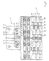
- FIG. 14 corresponding details are designated with reference numbers increased by 100 compared to FIGS. 2 and 5.
- the side view of the add-on housing 101 can be seen, which has at its ends flanges 125 for fastening the housing to a control cabinet housing or the like.
- the plug insert 102, of which the second part 105 is visible, is shown partly in view, partly with the cover part 114 being broken away.
- the peripheral frame part 107 is shown without breaking out.
- Parallel conductor rails 111 which branch into contact tongues 112, 112 ', can be seen below the broken-out area.
- clamping tabs 117, 117 'and clamping screws 116, 116' can be seen, only half of the illustration being numbered.
- the conductor rails each have laterally broken-out contact edges 133, into which contact clips 120 can be snapped in and can be used to produce a conductive contact between two adjacent conductor rails 111 lying in parallel.
- These contact brackets 120 comprise resilient conductor legs 134 lying in parallel. Four of these contact brackets can be seen in section in the previously discussed broken away representation.
- the openings 118, 118 'for the clamping screws and the openings 119, 119' for the insertion of the conductor wires can be seen. Between two rows of the openings mentioned, further openings 121 are arranged, into which the aforementioned contact brackets 120 can be inserted. In the view, four of the contact brackets 120 are shown with their handle parts 135 lying above.
- FIG. 15 Corresponding details are shown in FIG. 15 with reference numbers increased by 100 compared to FIGS. 2 and 5.
- the add-on housing 101 with flanges 125 with the through holes 124 can be seen, in which the plug insert 102 is inserted. This is inserted with its first part 104 into the through opening 103 of the add-on housing 101, and protrudes from the bottom thereof. The upper second part 105 does not extend in width beyond the cross section of the through opening 103.
- fastening flanges 126 screwed onto the plug insert are screwed onto the base 138 in the through opening 103 by means of screws 127.
- Sheet metal parts are fastened on the end face to the plug insert 102 and form a tab 128 which is equipped with a holding plate 130 and a clamping screw 131. Earthing or protective contact conductors can be connected to this tab.
- the plug insert 152 shows a plug insert 152 inserted into a conventional add-on housing 151.
- the plug insert 152 has screwed-on fastening flanges 176 which rest on bases 188 in the add-on housing 151 and are connected to the latter by means of screws 177.
- the bases 188 do not have threaded holes but through holes, while the screwed-on fastening flanges 176 are made of reinforced material and have threaded holes so that they can be screwed from the plug side.
- the plug insert 152 comprises a first part 154 inserted into the through opening 153 of the attachment housing 151, as well as a second part 155 which lies outside the attachment housing 151 and does not go beyond the open cross section thereof.
- the first part 154 merges in one piece into the second part 155. Longitudinal recesses are provided in the plug insert 152, are inserted in the conductor rails 161. On this, not shown plug contacts are pushed and z. B. crimped.
- the conductor rails 161 merge in one piece into connection contacts 167, 167 '. They also have middle contact tongues 183.
- the conductor rails 161 are punched out of sheet metal material.
- the connection contacts 167, 167 ' end in open insertion openings 169, 169' for suitable flat plugs.
- the contact tongues 183 are in the region of insertion openings 171 for contact brackets which will be shown later.
- the plug insert 152 of the form shown here has a first connection surface 163 with the openings for the contact inserts and two second connection surface parts 172, 173, which are coplanar and symmetrical to one another, with the insertion openings 169 for connection contacts, the connection surface 163 and the connection surfaces 172, 173 at an angle of 90 ° to each other.
- the plug insert 152 is shown in a side view, the attachment housing 151, into which the plug insert 152 is inserted, also being visible.
- the attachment housing 151 shows at its ends flanges 175 with which the attachment housing 151 can be screwed to a control cabinet housing or the like. It can be seen that the plug insert is constructed from first end-side washer bodies 156 ', 156 "and further washer bodies 156 which are identical to one another.
- washer body does not preclude the fact that in the end faces springs and grooves 196, 197 interlock.
- connection contacts 167, 167' which are designed as tongue-shaped sheet metal parts, stand free be plugged on.
- the plug insert 152 is shown installed in the mounting housing 151, the second part 155, which protrudes from the top of the through opening, does not extend in width beyond the cross section of the through opening.
- Screwed-on fastening flanges 176 of the plug insert 152 are screwed onto the aforementioned bases 188 of the attachment housing in the through opening 153 of the attachment housing 151 by means of screws 177.
- On the face side of the plug insert 152 these have metal tabs 79, against each of which a holding plate 180 can be pressed by means of a screw 181, grounding or protective contact conductors being able to be clamped between the parts mentioned.
- the plug insert 152 as a whole is made up of washer bodies 156 of the same type with one another and two front washer bodies 156 ', 156 "which each comprise the entire height of the first and second parts.
- the contact insert for contact pins or contact sockets protruding from the through opening below in contrast, is in one piece.
- FIG. 19a shows a section and a side view of a contact clip 170, which has a non-conductive handle part 185 and two resilient conductor legs 184, which are conductively connected to one another in a U-shape and are cast in on the handle part 185.
- the conductor legs 184 have expressions 187, their locking function has already been explained.
- FIG. 19b shows a modified contact bracket 170 'which accommodates three pairs of conductor limbs 184 in a single grip part 185, each of which is connected to one another in a U-shape. This enables conductive connections to be made between four pairs of connection contacts at once.
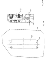
- FIG. 20a shows how two plug inserts 152 arranged parallel to one another are screwed onto parallel mounting rails 201, 202, the connection surfaces 163 of the plugs being recognizable.
- FIG. 20b shows the same details as in FIG. 20a in cross section through the carrier rails 201, 202. In this case, the coplanar mating surface parts 172, 173 are recognizable.
- FIG. 21a shows a sheet metal wall part 251 with a hole cutout 252 and screw holes 253 for inserting and screwing on a plug insert.
- 21b shows a plug insert 152 in vertical section, which is inserted in the sheet metal wall part 251 and fastened by means of screws 254.
- FIG. 22 shows a plug insert 352 and an attachment housing 51 in a similar construction as in FIG. 7, but here the second connection surfaces 372, 373 are inclined at an angle with respect to the first connection surface 363 and offset parallel to one another.
- FIG. 23 shows a plug insert 452 and an attachment housing 51 in a construction similar to that in FIG. 7, but there are the second connection surfaces 472, 473 are symmetrically inclined relative to the first connection surface 463 by an equally large angle, so that they form a roof shape with one another.
- FIG. 24 shows a plug insert 552 in an attachment housing 51 similar to that in FIG. 16.
- the second connection surfaces 572, 573 are coplanar and inclined by an angle deviating from 90 degrees with respect to the first connection surface 563.
- FIG. 25 shows a plug insert 652 and an attachment housing 51 in a similar design to that shown in FIG. 16.
- one of the two second connection surfaces 672 is arranged opposite the first connection surface 663, while the second connection surface 673 forms an angle of 90 ° with respect to the first connection surface 663.
Applications Claiming Priority (3)
| Application Number | Priority Date | Filing Date | Title |
|---|---|---|---|
| DE9302091U | 1993-02-13 | ||
| DE9302091U DE9302091U1 (ja) | 1993-02-13 | 1993-02-13 | |
| PCT/EP1994/000404 WO1994018725A1 (de) | 1993-02-13 | 1994-02-12 | Vielpoliger steckereinsatz |
Publications (2)
| Publication Number | Publication Date |
|---|---|
| EP0636281A1 EP0636281A1 (de) | 1995-02-01 |
| EP0636281B1 true EP0636281B1 (de) | 1996-11-20 |
Family
ID=6889383
Family Applications (1)
| Application Number | Title | Priority Date | Filing Date |
|---|---|---|---|
| EP94907557A Expired - Lifetime EP0636281B1 (de) | 1993-02-13 | 1994-02-12 | Vielpoliger steckereinsatz |
Country Status (5)
| Country | Link |
|---|---|
| US (1) | US5611710A (ja) |
| EP (1) | EP0636281B1 (ja) |
| DE (2) | DE9302091U1 (ja) |
| ES (1) | ES2097034T3 (ja) |
| WO (1) | WO1994018725A1 (ja) |
Families Citing this family (11)
| Publication number | Priority date | Publication date | Assignee | Title |
|---|---|---|---|---|
| DE29502186U1 (de) * | 1995-02-10 | 1995-03-30 | Weidmueller Interface | Elektrische Verteileranordnung |
| DE19513880C2 (de) | 1995-04-18 | 1998-07-09 | Whitaker Corp | Steckverbinder |
| DE19715437C2 (de) * | 1997-04-09 | 1999-02-11 | Siemens Ag | Elektrische Verteilervorrichtung mit Gemeinschaftsleiter |
| US6729913B2 (en) * | 2001-09-07 | 2004-05-04 | Rockwell Automation Technologies, Inc. | Network branch connector and method and system incorporating same |
| US7238063B2 (en) * | 2004-06-28 | 2007-07-03 | Alvin Dean Thompson | Field communication and computer data distribution system |
| US7625248B2 (en) * | 2004-06-28 | 2009-12-01 | Dt Search & Designs Llc | Field data distribution system with fiber optic converter |
| DE102007006138B4 (de) * | 2007-02-07 | 2021-10-14 | Bizerba SE & Co. KG | Geräteeinbaustecker |
| DE102008023979B4 (de) * | 2008-05-16 | 2010-05-12 | Wago Verwaltungsgesellschaft Mbh | Anschlussadapter |
| CA2849766A1 (en) | 2011-09-23 | 2013-03-28 | Dt Search & Designs Llc | Stackable cable reel with field data distribution system |
| US8829343B1 (en) | 2011-09-26 | 2014-09-09 | Dt Search And Designs, Llc | Cable connector seal kit with torque limiting spacers |
| JP5978106B2 (ja) * | 2012-11-08 | 2016-08-24 | 矢崎総業株式会社 | コネクタ間の接続構造 |
Family Cites Families (10)
| Publication number | Priority date | Publication date | Assignee | Title |
|---|---|---|---|---|
| FR742276A (ja) * | 1933-03-03 | |||
| US2911615A (en) * | 1957-10-01 | 1959-11-03 | Alltronics Mfg Co | Connector for electric wires |
| NL271983A (ja) * | 1960-12-01 | |||
| US3140139A (en) * | 1961-11-02 | 1964-07-07 | Grayhill Moldtronics Inc | Connector assembly |
| US3246208A (en) * | 1962-08-31 | 1966-04-12 | Leeds & Northrup Co | Programming pinboard |
| GB973983A (en) * | 1962-12-22 | 1964-11-04 | Automatic Telephone & Elect | Improvements in or relating to electrical connecting arrangements |
| GB1496799A (en) * | 1975-03-17 | 1978-01-05 | Hego Electric Gmbh | Electrical plug and socket connectors |
| DE3522797A1 (de) * | 1985-05-17 | 1986-11-20 | Brown, Boveri & Cie Ag, 6800 Mannheim | Elektrische vielfachsteckvorrichtung |
| US4898549A (en) * | 1986-01-28 | 1990-02-06 | Omron Tateisi Electronics Co. | Connector built from one or more single rowed housings, with long lasting locking mechanism |
| US5266043A (en) * | 1992-01-31 | 1993-11-30 | Augat Inc. | Fully programmable connector |
-
1993
- 1993-02-13 DE DE9302091U patent/DE9302091U1/de not_active Expired - Lifetime
-
1994
- 1994-02-12 US US08/318,829 patent/US5611710A/en not_active Expired - Fee Related
- 1994-02-12 DE DE59401067T patent/DE59401067D1/de not_active Expired - Fee Related
- 1994-02-12 WO PCT/EP1994/000404 patent/WO1994018725A1/de active IP Right Grant
- 1994-02-12 ES ES94907557T patent/ES2097034T3/es not_active Expired - Lifetime
- 1994-02-12 EP EP94907557A patent/EP0636281B1/de not_active Expired - Lifetime
Also Published As
| Publication number | Publication date |
|---|---|
| DE9302091U1 (ja) | 1993-04-22 |
| ES2097034T3 (es) | 1997-03-16 |
| WO1994018725A1 (de) | 1994-08-18 |
| DE59401067D1 (de) | 1997-01-02 |
| US5611710A (en) | 1997-03-18 |
| EP0636281A1 (de) | 1995-02-01 |
Similar Documents
| Publication | Publication Date | Title |
|---|---|---|
| EP0634888A1 (de) | Steckbare Baugruppe, insbesondere Relaismodul für Kraftfahrzeuge | |
| DE19632821C2 (de) | Verdrahtungsplatte für elektrische Verbindungen | |
| EP0451531A1 (de) | Elektrische Kontaktanordnung | |
| DE19614788B4 (de) | Anschlußleiste für hohe Übertragungsraten | |
| EP0636281B1 (de) | Vielpoliger steckereinsatz | |
| DE3928751C2 (ja) | ||
| DE202015106730U1 (de) | Stecker für Durchgangsverdrahtung | |
| DE3441416C2 (de) | Elektrische Steckverbindung | |
| DE4106412C2 (de) | Elektrischer Steckverbinder | |
| EP0933849B1 (de) | Einrichtung zur Stromversorgung | |
| EP0739060B1 (de) | Steckverbinder | |
| DE4431274C2 (de) | Verfahren zum Herstellen eines Elektro-Installationsgerätes sowie Elektro-Installationsgerät | |
| DE102009049489A1 (de) | Anschlussklemme und Elektroinstallationsgerät mit einer Anschlussklemme | |
| EP0086316B1 (de) | Steckkontaktvorrichtung zur Herstellung einer elektrischen Verbindung zwischen zwei Schienen | |
| EP3286803B1 (de) | Reihenklemme mit externem elektrischem bauelement | |
| EP0221839A2 (de) | Leistungsschalter mit einer frontseitigen Öffnung eines Isolierstoffgehäuses und einer Leiterplatte | |
| DE19963268A1 (de) | Sicherungsleiste, zugehöriger Sicherungskasten und Herstellungsverfahren | |
| EP1105939B1 (de) | Anreihbare busschiene | |
| EP0872913B1 (de) | Mehrfach-Koaxial-Steckverbinderteil | |
| EP1020954B1 (de) | Elektrische Anschlussklemme | |
| EP2608323B1 (de) | Gehäusedurchführungsverbinder | |
| DE10347306A1 (de) | Schirmanbindung | |
| DE19519634C2 (de) | Anschlußblock für Leistungskondensatoren | |
| DE10204934A1 (de) | Anschluß- oder Verteilvorrichtung für elektrische Installationsgeräte | |
| DE2116342A1 (de) | Elektrische Steckverbinder |
Legal Events
| Date | Code | Title | Description |
|---|---|---|---|
| PUAI | Public reference made under article 153(3) epc to a published international application that has entered the european phase |
Free format text: ORIGINAL CODE: 0009012 |
|
| 17P | Request for examination filed |
Effective date: 19940917 |
|
| AK | Designated contracting states |
Kind code of ref document: A1 Designated state(s): DE ES FR GB IT |
|
| 17Q | First examination report despatched |
Effective date: 19950608 |
|
| GRAG | Despatch of communication of intention to grant |
Free format text: ORIGINAL CODE: EPIDOS AGRA |
|
| GRAH | Despatch of communication of intention to grant a patent |
Free format text: ORIGINAL CODE: EPIDOS IGRA |
|
| GRAH | Despatch of communication of intention to grant a patent |
Free format text: ORIGINAL CODE: EPIDOS IGRA |
|
| GRAA | (expected) grant |
Free format text: ORIGINAL CODE: 0009210 |
|
| AK | Designated contracting states |
Kind code of ref document: B1 Designated state(s): DE ES FR GB IT |
|
| REF | Corresponds to: |
Ref document number: 59401067 Country of ref document: DE Date of ref document: 19970102 |
|
| ITF | It: translation for a ep patent filed |
Owner name: DE DOMINICIS & MAYER S.R.L. |
|
| ET | Fr: translation filed | ||
| REG | Reference to a national code |
Ref country code: ES Ref legal event code: FG2A Ref document number: 2097034 Country of ref document: ES Kind code of ref document: T3 |
|
| GBT | Gb: translation of ep patent filed (gb section 77(6)(a)/1977) |
Effective date: 19970227 |
|
| ET | Fr: translation filed |
Free format text: CORRECTIONS |
|
| PLBE | No opposition filed within time limit |
Free format text: ORIGINAL CODE: 0009261 |
|
| STAA | Information on the status of an ep patent application or granted ep patent |
Free format text: STATUS: NO OPPOSITION FILED WITHIN TIME LIMIT |
|
| 26N | No opposition filed | ||
| REG | Reference to a national code |
Ref country code: GB Ref legal event code: 732E |
|
| REG | Reference to a national code |
Ref country code: FR Ref legal event code: TP |
|
| REG | Reference to a national code |
Ref country code: ES Ref legal event code: PC2A |
|
| PGFP | Annual fee paid to national office [announced via postgrant information from national office to epo] |
Ref country code: ES Payment date: 19990219 Year of fee payment: 6 |
|
| PG25 | Lapsed in a contracting state [announced via postgrant information from national office to epo] |
Ref country code: ES Free format text: LAPSE BECAUSE OF NON-PAYMENT OF DUE FEES Effective date: 20000214 |
|
| REG | Reference to a national code |
Ref country code: ES Ref legal event code: FD2A Effective date: 20010910 |
|
| REG | Reference to a national code |
Ref country code: GB Ref legal event code: IF02 |
|
| PG25 | Lapsed in a contracting state [announced via postgrant information from national office to epo] |
Ref country code: IT Free format text: LAPSE BECAUSE OF NON-PAYMENT OF DUE FEES;WARNING: LAPSES OF ITALIAN PATENTS WITH EFFECTIVE DATE BEFORE 2007 MAY HAVE OCCURRED AT ANY TIME BEFORE 2007. THE CORRECT EFFECTIVE DATE MAY BE DIFFERENT FROM THE ONE RECORDED. Effective date: 20050212 |
|
| PGFP | Annual fee paid to national office [announced via postgrant information from national office to epo] |
Ref country code: GB Payment date: 20080227 Year of fee payment: 15 |
|
| PGFP | Annual fee paid to national office [announced via postgrant information from national office to epo] |
Ref country code: DE Payment date: 20080331 Year of fee payment: 15 Ref country code: FR Payment date: 20080218 Year of fee payment: 15 |
|
| GBPC | Gb: european patent ceased through non-payment of renewal fee |
Effective date: 20090212 |
|
| REG | Reference to a national code |
Ref country code: FR Ref legal event code: ST Effective date: 20091030 |
|
| PG25 | Lapsed in a contracting state [announced via postgrant information from national office to epo] |
Ref country code: DE Free format text: LAPSE BECAUSE OF NON-PAYMENT OF DUE FEES Effective date: 20090901 |
|
| PG25 | Lapsed in a contracting state [announced via postgrant information from national office to epo] |
Ref country code: GB Free format text: LAPSE BECAUSE OF NON-PAYMENT OF DUE FEES Effective date: 20090212 Ref country code: FR Free format text: LAPSE BECAUSE OF NON-PAYMENT OF DUE FEES Effective date: 20090302 |